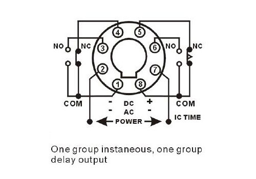
8 Pin Timer Relay Wiring Diagram. Wiring the relay creates a half bridge. You will learn completely in this video about its use, application,timer relay circuit.
Yet, with help from this how-to book even the neophyte mechanic can install a wiring harness.
The one automotive job we all dread is the wiring.
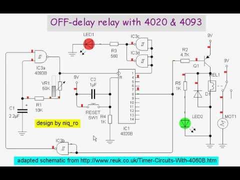
off-delay relay with 4020 & 4093 - YouTube

25x25U ★ 3 way switch wiring Beuler Relay Wiring Diagram ...

Bluetooth fm transmitter: MY ELECTRONIC CIRCUITS
Solid State Timer | Solid State Relay Timer | Electrical ...

Electrical relay animation. Electrical relay working ...
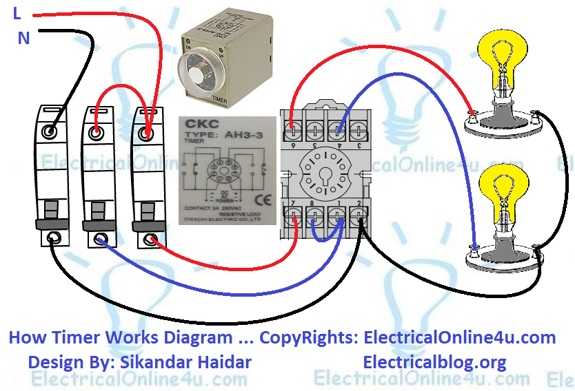
Electrical Online 4u

201A-9 - Symcom - Protection Relays | Galco Industrial ...
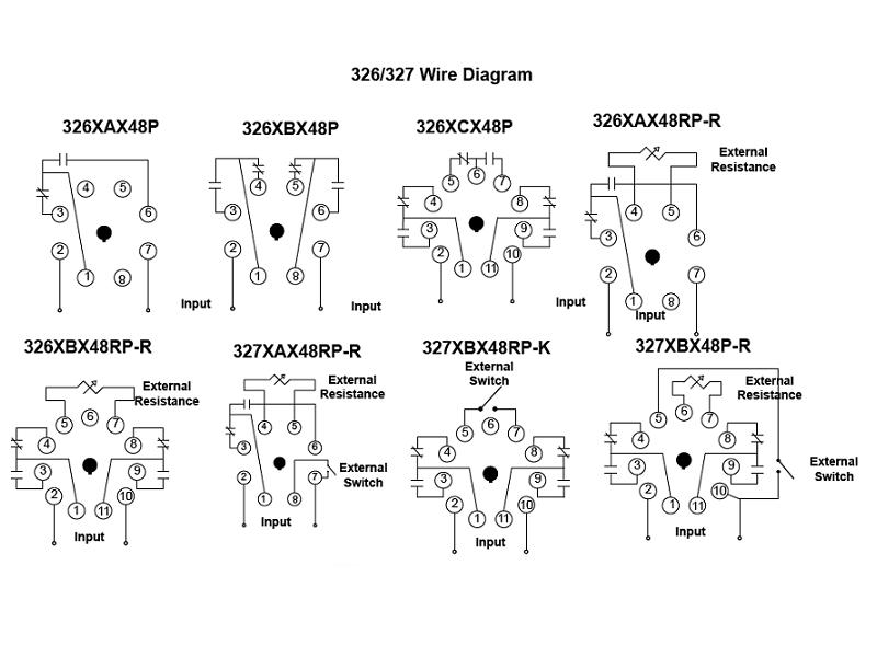
Item # 326XBX48P-010-115-125VDC, 326/327 Series - Time ...
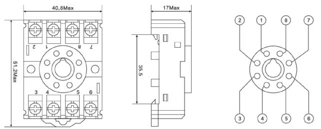
China 8 Pin Relay Socket Manufacturers and Suppliers ...
Wiring the relay as shown in the hookup diagram above does exactly what I want. The best use for the timer relay would be to provide a. digital overcurrent relay. digital display timer. digital relay timer. digital camera input. dell solid state. Circuit Diagram of a Versatile Programmable Timer.
